or the saga of an awful error
Published in Model Railways, April 1974.
About two or three years ago I was invited to visit the holy hiding place of the well known anchorite David Newham to discuss the awesome mysteries of Bulleid`s Leader Class. I arrived on the wrong evening and found myself in the singularly unlovely company of the Merioneth Railway Club. For the benefit of those who did not read Tony Jenkins` recent article, this group is devoted to the production of large scale models of two foot gauge (or thereabouts) to run on O gauge track. Upon better acquaintance I discovered that, in the best fairy tale tradition, beneath those unlovely exteriors there beat the proverbial hearts of gold.
Now a short while before I had produced a plastic injection mould for the Listowel and Ballybunion `A` frames for Don Boreham and he being one of the aforesaid unlovely etc.,etc,. Suggested that I produce some parts for the Merioneth group. I did so in due course and for the following six months I just went along , had a natter and made a few bits. This was fatal, I caught the narrow gauge bug and asked if I might join the group formally. The subscription being very moderate and the members not unfriendly I thought I would have no trouble getting in. Imagine my surprise when I was informed that this was a society for active narrow gauge modellers in 16mm scale and that, while I was very welcome as a guest, I must produce a 16mm narrow gauge model before I could join. I felt this was a bit harsh since by then about half of the group`s stock was running on my wheels.
However, rules are rules and I had to produce a model. The problem was what I should make? I realised that if l chose anything British I should be reminded continually of all the little errors on the model. What was needed was some remote prototype which they were unlikely to know more about than I did.
As luck would have it, I did possess a very poor photograph of an Otavi Minen & Eisenbahn Gesellschaft locomotive from German South West Africa. Built by Orenstein and Koppel in the early part of this century it seemed sufficiently remote to confuse even this group of fanatics.
l decided that my locomotive would be based on this.
The group was in its plastic era and busily converting Triang diesel shunters into 0-4-0 steam locomotives. Putting my big flat foot right in it, I enquired whether the group ever built any other wheel arrangement. The reply was unprintable.
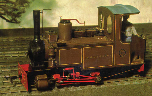
Later, at home, l sketched out what is now Persephone and for sheer devilment gave it an 0-8-0 wheel arrangement. Following the lead given by the other members of the Merioneth mob, I decided that this, too was to be a conversion based on a Triang diesel shunter.
From the foregoing it should be obvious that Persephone`s parentage is questionable to say the least. There the matter rested until a bout of stomach trouble kept me off work for a fortnight. During this time I made a start on Persephone and, since I could not get out in my garden workshop, adopted plastic construction. The basic structure of the body was carried out in 1/16in. polystyrene sheet for flatness and rigidity and the boiler rolled from several layers of thin sheet.
The only tooling worthy of note is the addition of a large thumb tack-type head to the embossing pin of a standard rivet punch which makes it very much more controllable on polystyrene sheet. This was very necessary because the engine is plentifully besprinkled with rivets in the best O & K style.
The smokebox was made a push fit on the end of the boiler so that the boiler could be used to contain two HP2 batteries. I should perhaps explain here that Persephone, as originally built, followed standard Merioneth practice whereby the loco. was battery powered utilising the original motor and chassis.
The reversing switch was connected to the reversing lever in the cab. Speed control was obtained by means of a model racing car hand control resistance mat mounted in the firebox, the wiper for which was connected to the regulator. In use the reversing lever was pushed into the appropriate running position and the regulator opened as in the full sized engine. This method of control is very pleasing but the large poking finger destroys the illusion, in my opinion.
The chassis of the diesel shunter underwent considerable butchery, the wheels were removed and replaced by my own moulded ones, the chassis sides were extended and new holes drilled and bushed for the axles.
Coupling rods were out of aluminium since the other members had found that heavy coupling rods resulted in jerky slow running due to lack of torque at low speeds. At this stage I recovered from my malaise and returned to work. Persephone was once again neglected. Some running tests were carried out on a short section of standard tinplate track and Persephone demonstrated her ability to negotiate a twelve inch radius curve. Not bad for an 0-8-OT.
At this stage the engine was painted. A totally fictitious livery of Brighton umber lined out in black and yellow and edged in dark brown was applied and the name Persephone bestowed upon her. This name was selected by my daughter who was doing Greek mythology at school. As she said, Persephone was queen of Hades and `that thing looks as if that is where it belongs.` She also said rude things about Father and his railways, but we will gloss over those.
That ought to have been the end of the story but l got dissatisfied with the idea of a plastic chassis and felt that a proper metal one was necessary.
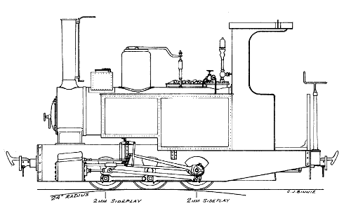
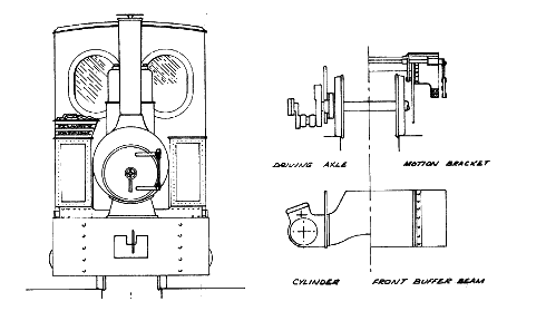
Closer examination of my rather tatty photograph revealed that it ought to be an O-6-OT with outside Stephenson`s or Allen`s straight link valve gear. Examination of other photographs of Orenstein & Koppel engines showed that this was a very common arrangement. What is more it was commonly associated with outside cylinders, outside frames and lovely outside balanced cranks. What a wonderful chance to do some lovely waggly valve motion. I had done Stephenson`s valve gear before in `S` gauge so l decided that this was going to have Allen`s straight link valve gear (see sketch). An added bonus was that the lifting links swing in unison when the valve gear is in forward gear but in opposition when the gear is reversed.
More drawings were produced showing each section of the valve gear and a valve event diagram prepared to prove that, even if the valve gear owed more to Binnie than to Orenstein and Koppel, it would behave in the correct style.
It was decided right from the start that the whole of the chassis should be made so that it could be completely taken apart for maintenance and painting. The chassis sides and the buffer beams were therefore cut out of mild steel and secured together by 14 BA hex headed bolts which passed through the buffer beam and into brass angles riveted and soldered to the, ends of the frames. The heads of the bolts were disguised simply: by placing them in the middle of a row of rivets. The leading wheels were allowed a degree of relative movement; not full compensation, l hasten to add, but enough to deal with the minor inequalities of the track. The salient points of the chassis design are shown in the sketch, while the method of silver soldering the various valve gear and motion rods was explained in a recent article (M.R. August 73).
The chassis literally came out of the scrap box, even the motor was an old manufacturers sample from work. To enable the chassis and motion to come apart, the outside cranks are pinned to the axles with 3/32in. taper pins. Withdrawal of these enables the cranks to be removed from the axles and the frames parted to release the wheels. Crank pins are pressed in to the cranks, shouldered, threaded and provided with special nuts to retain the coupling rods. The driving crank pin is squared at the end, while the return crank for the eccentrics has a square hole with a clamp bolt to secure it to the crank pin. Naturally, the centre of rotation of the eccentrics has to coincide with the centre of the axle.
To ensure this the roughly finished return crank was fitted to the crank pin and the return crank. The hole in the return crank was then drilled using the axle hole in the main crank as a guide. This entailed the use of a small drill bush to ensure concentricity.
The eccentrics look complicated but are very simply made. The rim of the eccentric is similar to the rim of a railway wheel, i.e. it has a small flange on one side. The flange is tapered at an angle of 45° and is about .010in. deep. The bore of the eccentric rim was reamed to ensure that they are all similar.
The eccentric bases were also turned to identical outside diameters. A simple calculation then established the dimension of the single spoke between boss and rim. All that had to be done was to file away one side of the boss so that boss and spoke just fitted inside the rim. A touch of soft solder and a quick clean up produced the eccentrics in less time than it takes to describe.
The eccentric sheaves and straps were made as described in Model Railways (August 73) and have the eccentric sheaves; reamed to suit the eccentrics. The outer faces of the sheave, i.e. the outer face of the outside sheave and the inner face of the inside sheave, were then lightly countersunk to match the flange on the eccentrics. When assembled, the small flanges; on the eccentrics prevent the sheaves from moving outwards while the other eccentric prevents the sheave moving inward. Following the policy of complete accessibility the eccentrics are secured to the return crank by an 8 BA screw which passes through the return crank and inner eccentric into a tapped hole in the outer eccentric. The slotted links were silver soldered together from two small blocks and two strips of nickel silver.
The cylinders came straight from the old plastic chassis and are made from plastic sheet with end covers injection moulded in nylon. That is really all there is to Persephone except that when it made its first track test on the Merioneth track at the exhibitions at Central Hall it persistently fell off the track on the curve, especially when pulling anything. The trouble was traced rapidly. The motor, etc., being mounted behind the rear axle left very little weight on the front wheels. The long overhang of the chassis behind the rear wheels meant that any train attached to the rear coupling promptly pulled the leading wheels up the outside of the curve. The cure was simple, more weight at the leading end and a re-location of the chopper coupling pivot from the rear buffer beam to a point just behind the rear axle.
That then is the story of Persephone. Not a locomotive I am particularly proud of, merely a locomotive of dubious ancestry but attractive appearance. It was good fun making it though. Perhaps that is what it is all about.
But what was that awful error mentioned in the title? I hear you ask. Well, after Persephone I was duly admitted to the Merioneth Railway Society and now most of the meetings are at my house. Mind you, they are a grand bunch of fanatics.