Article originally published in Model Railways in 1972.
Slate Wagon Production
At the recent (1972) National Model Railway Exhibition I was invited to take a place among the demonstrators, not, I hasten to add, like Anna waving the banner, but disguised as an honest British craftsman plying his trade. On the long demonstration stand and under the harsh rule of Norman Eagles (of Sherwood, clockwork and string fame) I spent a week trying not to display my ignorance to the over-knowledgeable customers.
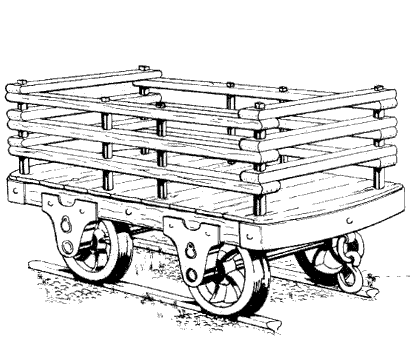
As a small dig at those of my fellows who return to this event annually with the same half-completed model, I decided to try and complete a few wagons at least. With this in mind, I produced a selection of jigs and other tools to enable me to carry out the work quickly. The wagon in question was the Festiniog Railway 2 ft narrow-gauge, wooden slate wagon and the aim was to model this in quantity to the scale of 16 mm/1 ft to run on gauge O track.
(I should explain that I am a member of the Merioneth Railway Company, a club specialising in large scale narrow gauge and numbering such stalwarts as Don Boreham and David Newham in its membership.)
The general appearance of this slate wagon is shown in the heading illustration and the construction of the models is of wood with metal fittings and axleboxes and wheels of Nylon. As this project tied in rather well with the general theme of `Production Methods` and does, at least, show that I use these methods myself, Roy Dock suggested that an account of the project would be in order.
The first jigs to be described are of practically universal application and, I must admit, it would be hard for me to manage without them now. For cutting sheet wood to width I use a short blade (the end of a hacksaw blade) screwed to the end of a piece of rod which is provided with a fence.
This time saver looks and is used like a carpenters scribing stock.
As the tools pop-up repeatedly when describing parts of the wagon construction, I proposed numbering them and inserting that number in brackets in the description as necessary. The modified scribing stock will, therefore be identified as (1).
The next tool is a modification of a carpenters tool also the modified mitre block (2) made from a piece of aluminum angle and supplied with an adjustable stop. In use, wooden or soft metal parts are cut to length using an X-acto razor saw in the fine slot and, for harder metals, a junior hacksaw in the broad slot.

2. Aluminum angle with adjustable block. Slots for saws.
.
The third tool is a simple assembly and drill jig consisting of a piece of brass plate to which scraps of rail have been soldered, making a shallow tray (3). The tray is about 1/64 inch wider than the finished wagon floor and about 1/4 inch longer. Eight holes are drilled through its base corresponding with the position of the uprights which pass through the `playpen` affair on top.
Now for the construction: as I am naturally lazy, I decided that as much as possible would be done in bulk. The sheets of 1/8 inch obechi from which the main structural members were cut were first sanded smooth on both sides and painted a faded red oxide colour (Humbrol track paint). When dry, the stripping stock/cutter (1) was used to reduce the sheets to 1/4 inch wide strip wood for the main underframe members and the cutting jig (2) used to produce the finished members.

4. Curved template locates in end holes of chassis
These were of two types; the centre member was 3/8 in. shorter than the finished wagon and the side member was cut 1/4 inch too long. (It will be noted that the frame members have their sides pre-painted and the top and bottom faces clean for gluing.) The heavy cross members at the end were cut in jig 2 also, but from 1/4 inch square wood.
With enough of these members cut to fill a box or two, attention was turned to the planks for the floor. The floors would have to be made up of individual planks, I decided, for l just could not get away with the usual piece of scribed sheet in this scale! A sheet of 1/16 inch thick obechi was cut into pieces across the grain, the width of which, when measured with the grain, was the same as the width of the wagon. A centre line was pencilled along the length of each strip. The cut edges of each piece were rounded of and smoothed with sandpaper. Using the stock cutter (1) set to the plank width, these pieces were reduced into individual planks rapidly. Two or three more boxes were filled with these!
The planks were laid with the pencilled centre line uppermost in the assembly tray (3) which retained them while the chassis members were glued in place; first the central member— along the pencil line—then the two end members and, finally, the sides. l used the new l.C.l. Dufix for this job and was very pleased with the result. The tray was then inverted gently, tipping out the embryo chassis and floor assembly to make room for another.
When the glue was dry the floor was sanded smooth and the assembly returned to the tray (3) for drilling. (In between times, a considerable number of chassis/floor assemblies had been made). Eight holes were drilled in the top face and the assembly returned to the pile. [Oh boy, Gloucester Carriage & Wagon had nothing like this. R.E.D.]
Now it was time to use a simple template (4) consisting of a curved piece of brass with two pins soldered into it. The purpose of the template was to enable the curve to be marked in with a pencil on the chassis/floor assembly when the latter had been positioned by placing the two end holes over the pins. The curve was cut using a fret saw blade in a piercing saw frame (much better balance and control) followed by a quick tidy up using sandpaper.
The cutting hook described in the November, 1971 issue of M.R. now came into play; once the sheet of .012 in. brass had been marked out and drilled, the hook soon reduced it to blanks for the metal end plates. A bending jig (5) was made up from a small scrap of metal, having a pin set at a certain distance from the end. To use this jig the metal blanks were located by their centre hole over the pin and the ends bent down.
The curve of the centre section was then pressed in with the fingers. The chassis/floor assembly was completed by pinning the end plates in position with gimp pins. The next job was to fit the metal strap for the draw gear. The strap is made of flat strip with an eye rolled at each end, and it is pinned along the underside of the central chassis member, providing a mounting for the couplings.

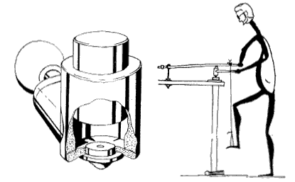
6. Rolling mill. Left roller on eccentric to adjust strip thickness
To obtain the strip l used the poor man`s rolling mill (6) to roll tinned copper wire. The device is not new and was described by Ernest F. Carter many years ago and more recently in one of our contemporaries. I make no apology for describing it again for it is a really useful device and neither of the earlier descriptions included means of adjustment. The revised version is shown in the sketch. To use, wire, with an end hammered flat, is passed between the guides and through the rollers. With the roller assembly secured in a vice, the end of the wire is grabbed with pliers and given a mighty heave. If all is well, a yard of gleaming, flat strip comes from between the rollers and may be clipped off. Grabbing the protruding end of the wire with the pliers, you give another heave, repeating the processes until the end of the reel is reached, or the workshop is full of flat strip. Take a good stance before heaving, for should the wire break you may end up sitting on the floor, waving the pliers and broken stub of wire like a dentist celebrating victory over a molar. A length of this strip is formed around the two pins on jig 7 to produce the afore mentioned draw gear strap.
Two pins pressed into a scrap of aluminum provide the hook former (8) for making the coupling hook. Wire was wound into this figure of eight fashion and clipped off to form the hooks as shown in the sketch. When squeezed flat between the vice jaws it made quite a presentable hook.
The chain link was also formed from wire by winding a coil around former (9) and cutting the coil lengthwise with the razor saw. These are assembled between the hook and the eye on the draw gear strap!

8 Hooks formed around pins. 9 wire wound on former to make links
The next job was to make and fit the running gear. The axles were cut to length from 3/32 inch silver steel using the ‘mitre block’ (2) and a hacksaw and the ends rounded off. I should like to digress here to express my thanks to Messrs`s and Bonds`. During the show I tried to buy further supplies of silver steel, alas no one had any at the show. Bonds took the trouble to telephone their shop and arrange for some to be sent to Central Hall for my special benefit, whilst the ever helpful Ken Keyser of K’s took the trouble to call in at his factory at Willesden and collect a large number of motor armature spindles from which I could cut my axles. In neither case was I charged extra for this service. Ken indeed refused any payment at all. With traders like this in the business I think the commercial side of our hobby is in good hands and would like once again to express my heart-felt thanks.
Now for the wheels and the axleboxes, these were both injection moulded in glass filled nylon. The injection moulding process, for those who have not met it before, is a method whereby granules of plastic are contained in a cylinder, melted and injected under pressure into a metal or other solid mould. The cylinder on my own unit is machined out of a piece of brass bar and has an internal diameter of 7/8 inch and a general wall thickness of 3/16 inch.
In the bottom of the cylinder is inserted a steel nozzle with a conical end having a bore of 3/32 inch. The cylinder is silver soldered to the end of a 120 watt electric soldering iron of the broad bit pattern, which provides the necessary heat. (Do please dismantle the iron and remove the element before doing the silver soldering!)
11. Ultra simple moulding rig
The cylinder is provided with a piston which can be removed to insert the plastic granules. Fig. 10 should explain what is meant. In use the nozzle is placed in the recessed end of the in-gate or `hole for squirting` in the plastic after which pressure on the top of the piston forces the molten plastic into the mould where it promptly solidifies. I now use a small arbour press for applying pressure to the top of the piston but when first experimenting I used the set up in Fig.11.
This explanation of the moulding process is deliberately brief since I have described it all before in the June, July and August 1968 issues of the old M.R.N. and propose to amplify these notes in a future article taking plastic moulding a little further.
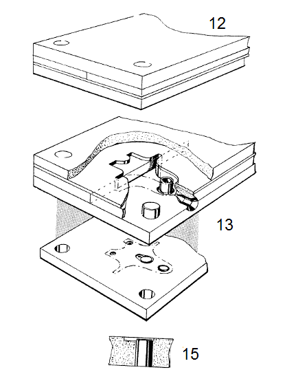
The mould for the axle boxes is part of a multiple mould built up from metal plates. The basic mould assembly consists of two outer plates of 1/4 inch thick mild steel between which is sandwiched a plate of 18 swg (3/64 or 0-048 in. thick) brass and a 1/8 inch thick brass plate split down the middle. (Fig. 12). This joint must be a close fitting one. The plates are dowelled together with 1/8 inch dia silver steel pins to ensure their relative location when assembled.
Into this assembly is cut the mould cavity as shown in Fig. 13. Points to note are the way in which the projecting lid of the oil box is formed in the outer plate by drilling a hole of the appropriate diameter.
Lightly countersinking the edge of the hole, forming the upper portion of the lid cavity by driving the flat end of a pin punch into the steel adjacent to the hole and carefully removing the resultant burr. The hole is then closed by driving in a close fitting peg with a small chamfer on the end. The combination of the countersink and the chamfer produce the small raised rim around the lower part of the box lid (Fig 15). The final touch is given by drilling a shallow hole to represent the head of the bolt on which the lid swings. The heads of the bolts which secure the axlebox to the under-frame are represented by small depressions punched in with the pin punch to represent the washer and a shallow hole drilled in the centre of this to represent the bolt heads.
The mould for the curly spoked wheels was a little more complex and I am going to defer this to the plastic moulding article mentioned above. The wheels were made a press fit on the axles. Here I hang my head in shame. I left the back to back gauge at home and had to set all the wheels with the aid of a rule! Ah well, you don`t win them all. The axleboxes with the wheel and axle assemblies were duly fitted in place and glued with Dufix. This adhesive does not adhere well to the nylon from which the axleboxes are made but it did hold them long enough to enable me to ensure that the wheels turn freely and to drill the two holes for the fixing pins.
All the holes in the wagons were, naturally enough, drilled with the home made drills that I described in these pages a few months ago. And thereby hangs another story. About two months ago I received a letter from a modeller with a most harrowing tale to tell. He had decided to follow the instructions and make some small drills out of piano wire as suggested. His difficulty was the piano wire. His local iron monger had never heard of the stuff and helpfully re-directed him to the local music shop where they had no idea what he was talking about. Piano wire may have some connection with piano strings but to the engineer it means a particular type of very hard spring steel wire. If this cannot be obtained, a good substitute for making drills is the domestic sewing needle which can be bought in many sizes right down to about 0-009 in. dia.
The very small ones are used for sewing sequins and such other peculiar tasks. The use of needles will put the cost of the drills up enormously however, they will cost about fifteen pence a dozen instead of about three pence a yard.
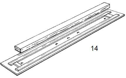
This completes the underframes of the wagons leaving only the play pen on top to be made. More of the pre painted obechi sheet was cut into strips with the stripping/scribing block (Fig. 1). This was rapidly reduced to side and end members by a combination of razor saw and the cutting jig (Fig. 2). These were then put in a simple drill jig (Fig. 14) and the holes drilled for the uprights.
The extremities of the side and end members were then rounded off with abrasive paper. For the uprights I used 1 1/2 inch long plated pins and cut the spacers which fit between the members from 3/32 inch outside dia. copper tube, using razor saw and cutting jig again. When the rather tedious assembly of the playpens was completed, the projecting points of the two central pins on each side were clipped off about 3/32 inch from the spacers leaving the four corner pins as sharp points. These were engaged in the holes previously drilled in the floor assembly. The vice was now used to gently press the pins home, in rotation, a little at a time until the lower spacers were snug up against the floor. A quick check to ensure that the wagon was not twisted in this final assembly and up on the shelf it went.

The final tally was twenty-one wagons during the exhibition of which eight lacked the upper rails. The total working time at the exhibition was about fifty six hours and the time spent making jigs, moulds, etc. was approximately a further fifteen hours. This works out at approximately four hours for each wagon from the rawest of raw materials to the finished and partly painted wagon including jigs, tools, etc. described in this article. It should be realised however that this was under exhibition conditions where there are modellers queries to be answered and where all holes have to be drilled the hard way- by hand.