This month`s screed does not deserve the title Production Methods since I do not propose dealing with anything new or particularly suited to the production of parts by the hundred. In fact, I will enlarge on a very simple subject which appears to be causing concern for many modellers and on some simple jigs that make life easier.
The problem of dealing with well known processes in a simple manner is not in explaining the process itself but in fending off the reader who, with access to other more technically detailed accounts, must leap into print and display his morsel of knowledge. The purpose of the exercise surely is to impart the essential information necessary to aid the production of model railways and to do so as simply as possible. That is enough of my irritated effusion, however, so let`s get to work. The subject this month is silver soldering.
The art of silver soldering is not as commonly practised by railway modellers as it should be. Indeed, l know several very well known and extremely competent modellers who still regard it as a black art. l suppose this is because they classify anything in which the components approach red heat as something akin to the blacksmiths art. This is just not so. The whole process of silver soldering is no more difficult than that of soft soldering, even if a little less universal in its application.
By the use of a modern propane/butane self contained blow torch the job can be done on the kitchen table if need be. The blow torch I use is the Ronson. This produces a flame adjustable from a broad soft flame of about 3/4 in. diameter to a short, very hot needle flame of about 1/8th in. diameter. The Gaz blowtorch is also recommended. This produces a larger flame and is not so well balanced as the Ronson nor does it produce the needle flame which is needed for some of our finer work. Refills for both Ronson and Gaz are available readily, those for the latter type being considerably larger and certainly make the Gaz blowtorch cheaper to run. Provided the torch is lit at the last moment and turned off as soon as the joint has been made, however, the cost of running either of these torches is very low indeed.
Now, to silver soldering. The term silver solder refers to a form of soldering carried out at dull red heat using a silver bearing alloy. It is one of many forms of hard soldering, which is the generic term for these processes. Brazing is the other really common one, whereby brass is used as the solder. This is useful for joining large pieces of steel but since it requires more heat than silver ‘solder is not much use to the railway modeller, as opposed to model engineer. A process which melts brass to use as solder is not likely to be much use for joining small brass parts anyway!
The two silver solders I recommend are Johnson Matthey‘s ‘Easyflo’ and ‘Easyflo No 2. Both of these are very good indeed, although I prefer to use ‘Easyflo’; it does require a little higher temperature (630°C) but contains more silver and seems to flow more easily. Both solders are obtainable as rods. wire and sheet. There is available also a silver solder paste from the same source.
The flux can be borax, though again I recommend ‘Easyflo’ flux. it seems to melt and flow more easily than borax and it is much simpler to clean off the joint. The metals which can be silver soldered easily include iron, steel, brass and nickel silver.
The procedure is as follows: The two parts are propped up in their correct relative positions and the joints anointed with a mixture of flux and water. I used to keep a little drop of strong flux solution ready made up, but it always seemed to dry up when I wanted it. Nowadays, I spit on the joint and put a tiny spot of the powdered flux on top. A small snippet of silver solder, about the size of a pin head, is placed against the joint and the joint heated to redness. The flux melts first and at this point care must be taken not to heat the joint too rapidly, particularly if the component parts are not too well secured; the heat causes the moisture to bubble violently and can disperse the parts. The flux having melted safely, the full heat is applied until the silver solder melts and ‘flashes’ into the joint.
The heat is then removed and the joint allowed to cool. If a small pot of water is kept handy, the joint can be allowed to cool until it is black and then finally quenched in the water. This has the effect of causing the rather brittle flux layer to crack off and disappear.
Before we go on to discuss some simple jigs perhaps I should stress that since silver solder is carried out at red heat, it is better suited to making joints in rods and such things than for soldering together the edges of large, thin sheets. The temperatures reached when silver soldering will almost certainly cause buckling of the sheet.
The most useful jig I possess is really very simple. It is just a piece of 3/4 inch thick asbestos block with some holes tapped in it.

The job to be soldered is laid out on the asbestos and a variety of bent wire clips (modified paper clips) is used under the screw heads to hold the parts in place while soldering is carried out. Typical of the parts made readily by silver soldering are spring hangers of the ‘U’ type. fork ends of all descriptions and locomotive steps.
For example, the tremendous strength of a silver soldered joint enables one to achieve really small secure butt joints in brake gear components. Fig.1 shows a couple of fork ends and fig.2 the method of construction I used recently to make some eccentric rods complete with sheaves.
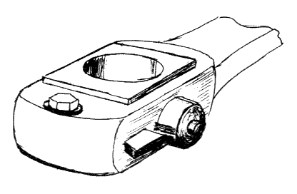
The locomotive footsteps mentioned above merit a few words, referring to fig.3. The first stage is to bend up the edge of a strip of brass to form the lower step. A second strip of brass, the same width as the top step, is cut and the ends bent to ensure that the step is at right angles to the top plate.
It will be seen that it is possible also to use these bent ends to ensure that the step is the right distance above the lower step. The joint is silver soldered. The steps may now be cut from this assembly and any small details added to taste. The sheet used should be about .020 in. (1/2 mm) thick. By chamfering on its rear edge it is a simple matter to reduce the apparent thickness.
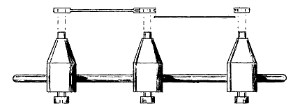
Simple Coupling rod jig
A simple jig for making coupling rods is shown in fig.4. All it consists of is a length of 1/8 inch diameter rod on which are mounted three adjustable bosses. The business end of each boss is a spigot of the same diameter as the axles used on the locomotive. In use, the bosses are adjusted so that the ends just enter the axle holes in the frames. The coupling rod bosses are made up and mounted directly on to the spigots.
The intervening sections of rod are fitted and the whole coupling rod silver soldered together. After a small amount of trimming, the result is a set of coupling rods of truly accurate centres which is far neater than I, for one, can file out of the solid. The oversize holes in the coupling rod bosses then accept flanged brass bushes, the heads of which may be filed square to represent the full size brasses.